Gate Project Overview
When we purchased our house, it came with a gate at the end of the driveway controlled by a Sentex Crown Jewel keypad. The keypad is programmed over 300 baud modem via the Win98 software CJWin32. While it is possible to run this software under a VM on my Mac, I wanted to try building a replacement as an excuse to learn PCB design. It would absolutely be trivial to replace the gate computer with a Raspberry Pi or similar, but that would defeat the point of the project as an educational exercise.
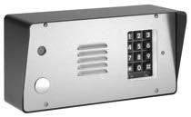
Crown Jewel
The existing gate controller:
Enclosure:
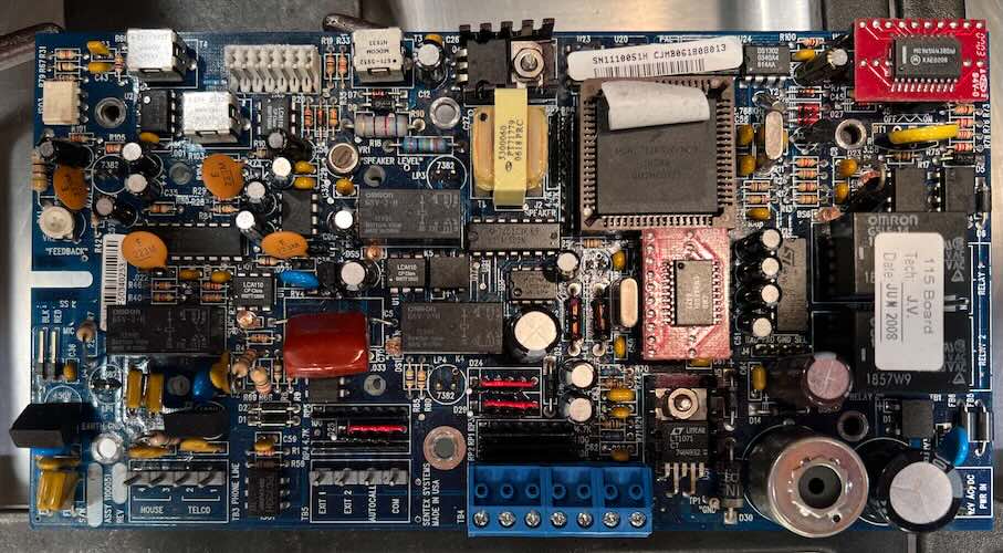
Hardware
The board design dates to roughly late 2003, and consists of a variety of components:
- MCHC711KS2CFNE3 HC11 Microcontroller
- MC145443B 300 baud modem
- LT1071 Switching regulator for phone line power
- Circuitry to generate ringing voltage and function as a line card
- 4 lamps to side-light the internal keypad at night
- 2 keypad interfaces (internal + external)
- A speaker, mic, and audio mixer connected to the phone line.
- A realtime clock/calendar to keep track of the weekly schedule.
Requirements
There were a number of things I wanted to be true of the replacement:
- The keypad is at a substantial distance from the house, it is in a metal enclosure, and I wanted the networking to be reliable, so I wanted to use Ethernet not WiFi.
- The existing solution requires a 12VAC or 12VDC power supply to the board, but since we’re using ethernet anyway, we should use PoE.
- The 12V incandescent lamps are replaced by LEDs to avoid annual changes.
- Keep the existing phone-line based intercom system, so we still need a speaker, microphone, and phone line interface.
- We need to support the existing keypad.
- Gate status should be relayed over HomeKit or Matter, and programmable via a web app or other simple interface
Decomposition
Generally the strategy for engineering projects is to break complex tasks down into manageable pieces. So, I decided to break the project into six hardware sub-projects. After solving each problem individually, they can be integrated together into a product.
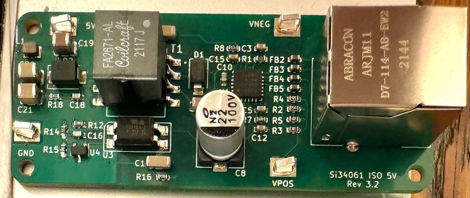
PoE
Started with Power over Ethernet, with a goal of supplying up to 5W at 5v, with an Isolated power design. The goal for final project was to allow the board to be powered via either USB VBUS or PoE and allow both, and be designed as if the goal was to pass regulatory and safety compliance for a device connected to an outdoor ethernet and phone line. For this project I had initially selected and designed the board around the Silicon Labs Si3406. The Covid parts shortage forced me to switch to the similar (and in some ways, better, but more expensive) Si34061 part way through the project, so I now have designs for both.
LED Lighting
The keypad on the original part was side lit by 4 12V incandescent bulbs, which require changing every couple years in addition to being power inefficient. This project’s goal was to both validate the relatively simple single-string design of 4 LEDs off a constant current source, and teach my older kid about PCB design. We ended up choosing the TI LM3410 for this project along with 3030 LEDs and some plastic light pipes to reach the height of the original bulbs in their lamp holders.
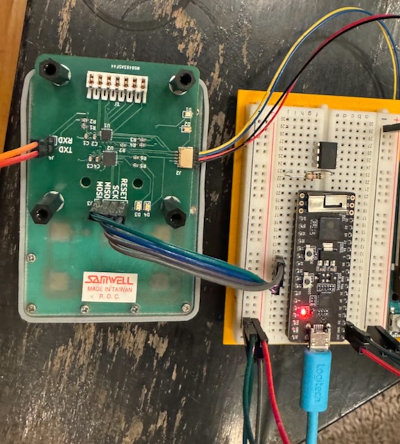
Keypad
This phase of the project was about matching the physical compatibility of the original enclosure, and reading the keypad with the TCA8418. The goal was also to validate the GPIO expansion capability of the TCA8418 since the ESP32 main micro was running out of GPIOs at this point in the design.
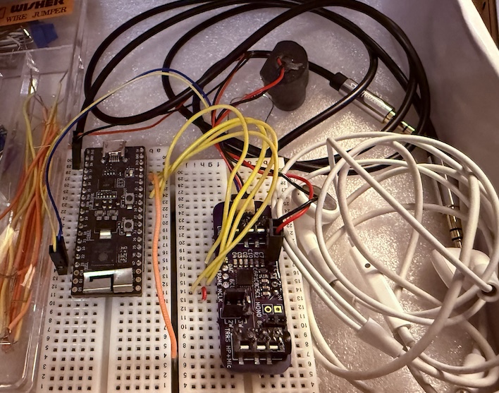
Audio
Moving on to audio, the goal was to support a microphone and powered speaker over i2s from the ESP32. For this project I selected the Wolfson WM8940 mono audio codec. The main challenge for this project was supporting MCLK = BCLK and driving both off the same ESP32 GPIO, since we were out of output-capable GPIOs, and the main clock generator on the ESP32 was in use to generate the 50MHz ethernet clock.
SLIC
To support the intercom, we also need to provide a Subscriber Line Interface Circuit (SLIC) and relays, so that we can disconnect the house from AT&T copper lines and pretend to be the phone company to ring the house, and send and receive audio over the copper pair. This means we need to generate both the 48VDC Tip-to-Ring voltage of the phone line, and the ~70VAC ringing voltage when ringing the house when someone is at the gate.
Networking
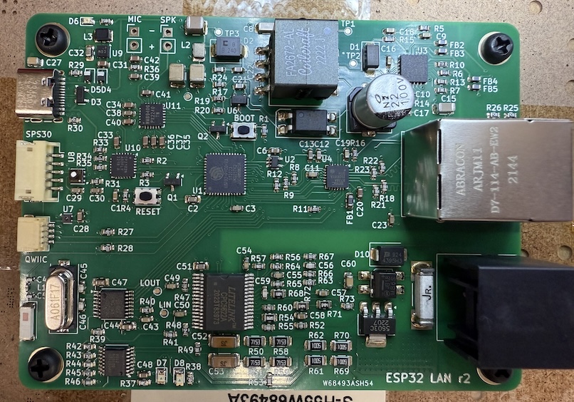
When I started this project the goal was to build on the previous ESP32 project which I enjoyed writing software for. The core here would remain the ESP32 with ethernet MAC coupled with a Microchip LAN8720A RMII PHY. In the end, between RMII, I2S, I2C, SPI, and other required strapping and GPIO functionality, we ended up using every available pin on the ESP32-PICO-V3-02.
Summary
In future posts i’ll talk more about each of these projects in turn (some are complete, some still require some debugging), and putting it altogether for the final product.